Working with registers
Содержание
General information
In the world of industrial automation, 'Registers' are understood as units of data that are attributes of automation equipment. They can describe some external parameters of technological processes (the value of temperature, pressure, flow, state of actuators, etc.) or internal states of the devices themselves (parameters of regulators, filters, alarms etc.).
Registers in the WEBHMI project correspond to similar concepts in automation systems - 'tag', 'variable' and indicate what data from the respective devices we are going to work on (read / write), in addition, they have additional attributes controlling how they will be displayed and processed by the system settings of these registers. The registers can be of two types - internal (from internal WebHMI memory) and external (containing data from connected devices). Register settings allow you to specify:
- The name of the register, the connection, network address, temporarily disable the register, i.e. exclude it from the polling list.
- Data type (bit, byte, word, etc.), format (integer, with floating point, signed, etc.), units. The measurement of the scale and shifting coefficients, the limits of the allowed values, the limits of the values entered by the operator, decimal point place, the dictionary (set of matching pairs like "raw raw regiser value - dictionary item")
- Set up a register entry in the log and on charts
- Set 4 alarm status (colorising) for registers - off, normal, warning, alert. In this case, visual elements (text, icons) and data in the log change color according to the register's state.
Create a register, basic settings
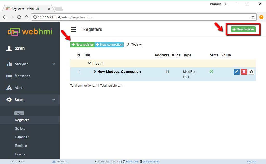
To create a register, go to the Setup-> Registers menu and click the Add New Register button.
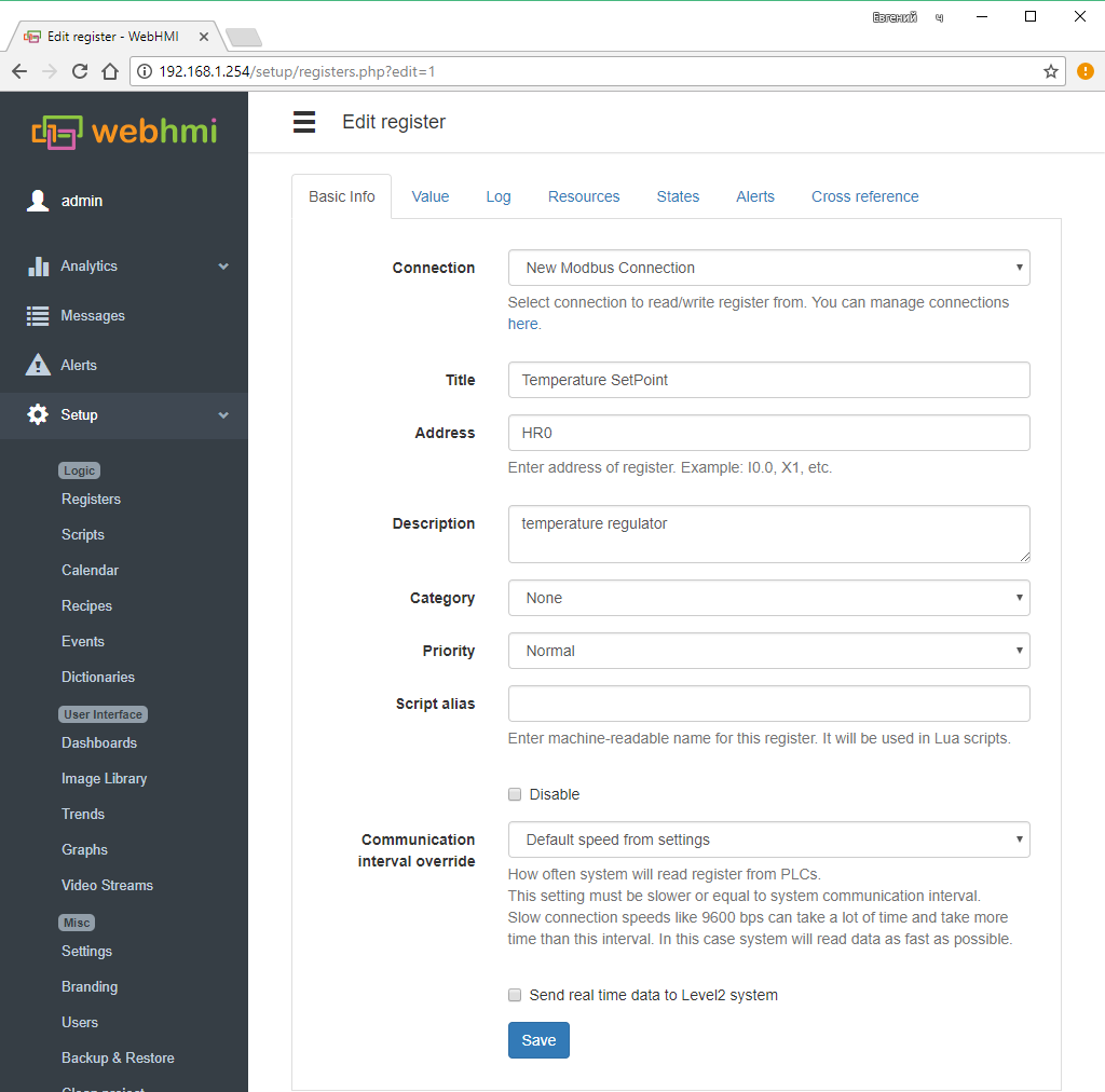
Then in the Basic info tab it will indicate:
- Title register's name
- PLC connection the registers belongs to
- Register address The address in the address space of this connection. While entering value, the address validation is being made. Address assignment formats are described [here].
- Description - description field for the register
- Category - the name of the group to which the register will be included.
- Priority - polling priority. This option is used in conjunction with the Strict scan function. Registers with high priority will be polled first, registers with priority normal in the second turn. If part of the registers with normal priority does not fit during the scan, this part is polled in the next scan, etc. Registers from internal connections are polled last (after registers on external connections) regardless of this setting, since they are read quickly on the local bus of the WebHMI device.
- Script alias - This name can be used in lua scripts.
- опция Disable - disables polling this register.
- Communication interval override - Override the default polling time for this register (Setup / Settings menu). Adjustable in steps of 500 ms. Up to 1 hour.
- Send real time data to WebHMI cloud - Specifies whether to send data to the cloud-based level2 system.
Setting the type and format of register data
Value tab of the register edit page is used to set the type and format of register data. These settings affect how the read binary data from the registers of the connected device are interpreted for display or recording.
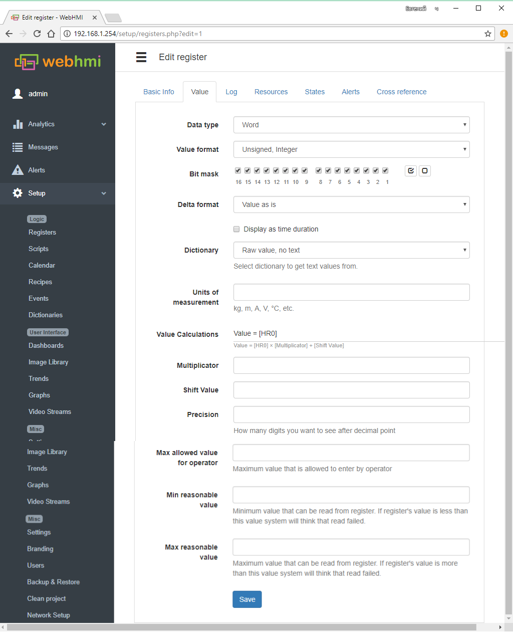
settings explanation on the above picture (start):
- Register Data Type - Data type:
- Bit - bit value,
- Byte - byte data size
- Word - word data size
- Double Word - double word data size
- Unix time - time format used in PHP, is set as Y-m-d H:i:s, e.g., to display the date as day - month - year (DD-MM-YYYY), you set like this d-m-Y.
- Register Data Type - Data type:
To read double words in reverse order (some devices work in this format), the option 'Reverse word order' is provided.
- Value format - Specifies the format of the read data.
- integer- unsigned or signed.
- fixed point float with sign (range of -1..+1) and without sign (0...1) (signed / unsigned)
- Two's complement
- Signed floating point, according to IEEE754 - 24 bit(such format is used in OWEN devices e.g.), 32 bit (ПЛК uLogix Allen-Bradley, Delta Electronics etc. ), 32 bit float with reverse word order
- Bit mask - When setting the bitmask to the register, the value corresponding to the weights of the selected bits will be calculated. Description of settings in the lower figure (Continued):
- Delta format - Allows you to convert register data into increment or derivative. In the first case (delta value), the register will be equal to the difference of the current subtracted value and the previous one. In the second (Delta value / Delta time) - too, divided by the time between polls, i.e. Derivative with respect to time.
- Display as time duration - Show the number in seconds in the format of the length of the time interval (hours, days, etc.). The format is useful, for example, when displaying the duration of events.
- Dictionary - Dictionary. Contains the enumeration of pairs 'value, word', when you select a dictionary for the register, the values read from the device are compared with the data of the dictionary and, if the word matches, the word corresponding to the value will be found. If there is a mismatch, the register will contain the value itself. The dictionaries are created and edited in the menu Setup -> Dictionary
- Units of measurement - Indication of engineering units for the register data. The string specified in the field will be displayed after the text string with the register value on the dashboard.
- Value Calculations - Scaling with offset data in the register. Used to bring the scales of the read data, for example from the ADC to the engineering units. The data are converted according to the formula:
- result = [value read ] х multiplier + shift value
- Multiplicator - multiplier
- Shift Value = offset
- Precision = The number of digits after the decimal point for the values of the float. point type.
- Min/Max Allowed Value For Operator - These fields allow you to limit the min. and max. possible value for the register, which can be changed by the user from the dashboard.::
- Value format - Specifies the format of the read data.
Min/Max Reasonable Value - These fields allow to designate a zone of unreliable values of the register, thus it is possible to judge the sensor failure. When reading the value outside the zone, a zero will be written to the register, which in turn can be defined as a 'disabled state' - see below.
Setting up a register write in the log and graphics
Registers have settings that allow you to write them according to certain rules in the log and graphics.
Writing registers to the log
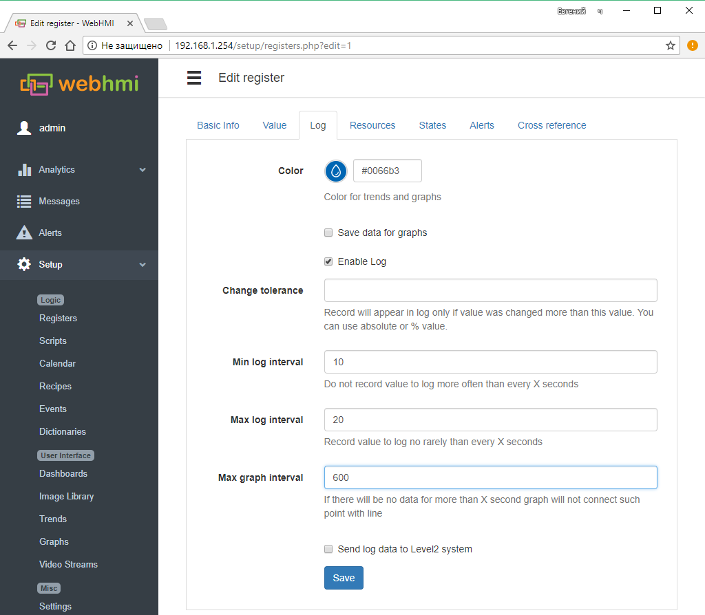
After selecting the option 'Enable Log' in the register settings, you can track its changes in the menu item Analytics / Registers Log. Logging settings :
- Color for trends and graphs - Selecting the color of the register data on the trends and graphs
- Change tolerance -'Tolerance' (absolute value or %) is the difference between new and previous register value, , if exceeded, its value will be written to the log. If the field is left blank, the record will occur upon any change. The recording frequency will be determined by the settings of the following items.
- Min log interval - serves as a filter for data, limiting recording frequency to this interval, so that time between two records will not exceed this interval
- Max log interval - If the register did not change its value, or the changes were within the 'tolerance', then this setting nevertheless allows writing the register to the log after the interval specified in the input field has expired in seconds.
- Max graph interval - Log data can be a source for historical graphs (see register settings for recording on the graph below), then if there was no data within the specified interval, the graph will have a corresponding gap.
- 'Send log data to Level2 system allows sending log and graph to level2
To configure the output of information in the log, see System information and log
Saving registers for graphs
After selecting the option 'Save data for graphs' in the register settings, you will be able to specify the recording frequency for graphics and choose the color of the register data display on the graphs. There will also be an option to transfer log data to the level2 cloud developer's site.
- Time interval - Frequency of recording on graphics, there are options: 1 hour, 15,5,2,1 min., Use data from log
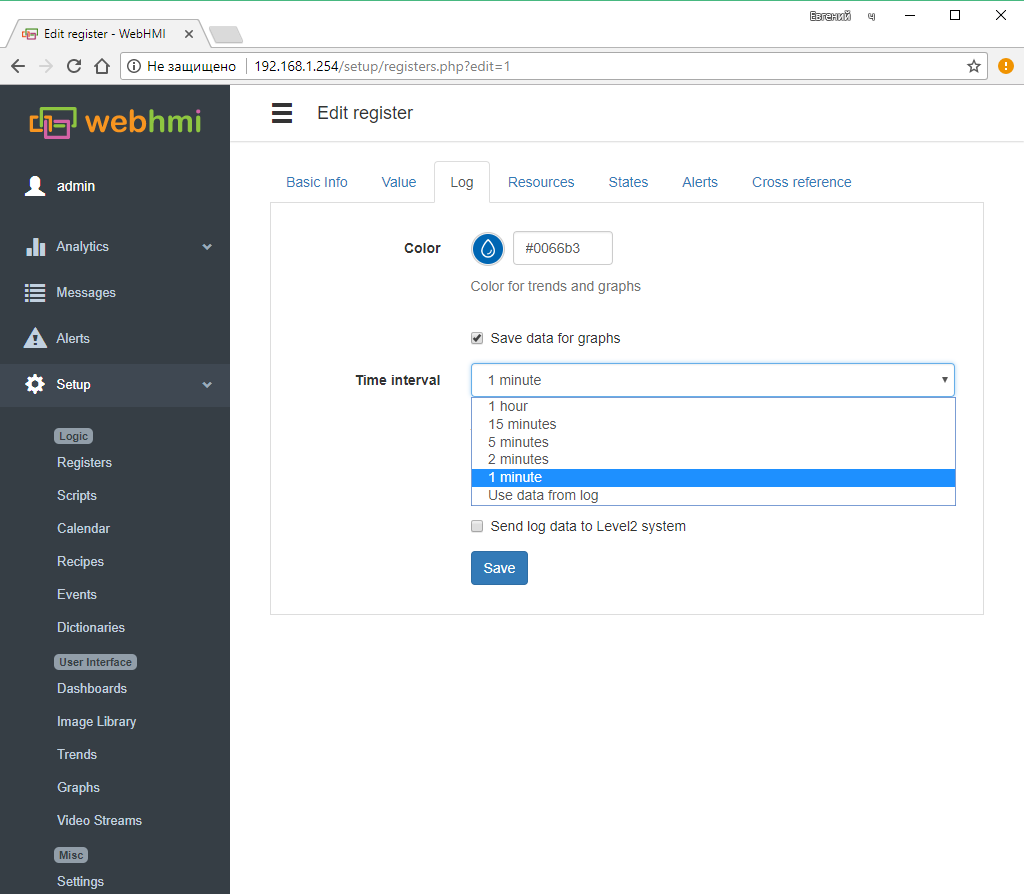
To save changes in the register, use the button Save.
Configuring states
The States tab of the register editing menu allows you to set 4 color alarm states for the corresponding specific values read from the register:
- Disabled state - 'Off', the data in the register indicate that the mechanism is off, the sensor is off (or an open circuit, for example, for a signal of 4..20mA is less than 4mA), there is no working pressure, etc. The default alarm color is gray
- Normal state - 'Norm', the value corresponding to normal operation. The default alarm color is green
- Warning state- 'Warning', the parameter approaches the dangerous boundary. The default alarm color is yellow
- Alert state - 'Emergency' - the alarm status of the parameter. The default alarm color is red.
When disabled, the value of the register on the instrument panel will be displayed in black.
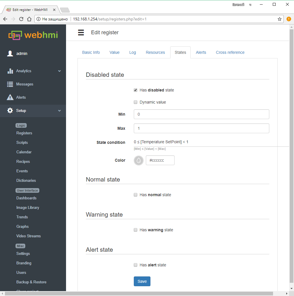
Setting the value limits for each of the states can be static and dynamic.
- With static (default) setting, the range of register state values is determined by the formula:' 'Min <= (register value)
- With dynamic setting Min. and Max. are also parameters specified in the form of other registers, and thus, for example, depending on the recipe of the produced product, the warning and emergency zones will change.
An example of dynamic configuration of the warning(Disabled state) state:
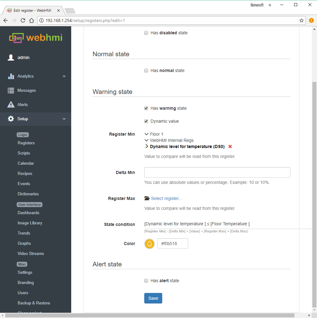
Here, the Minimize shift and Maximum shift are the offsets from the lower and upper bounds of the warning status zone used in the formula (specified with REgister Min., Register Max, given for convenience here in the interface.)
Working with a list of connections and registers
The list of registers is multi-level, when you minimize the list, only the list of connections is displayed.
When the cursor selects the connection to the right of it, a checkbox appears to select or deselect all registers in the connection.
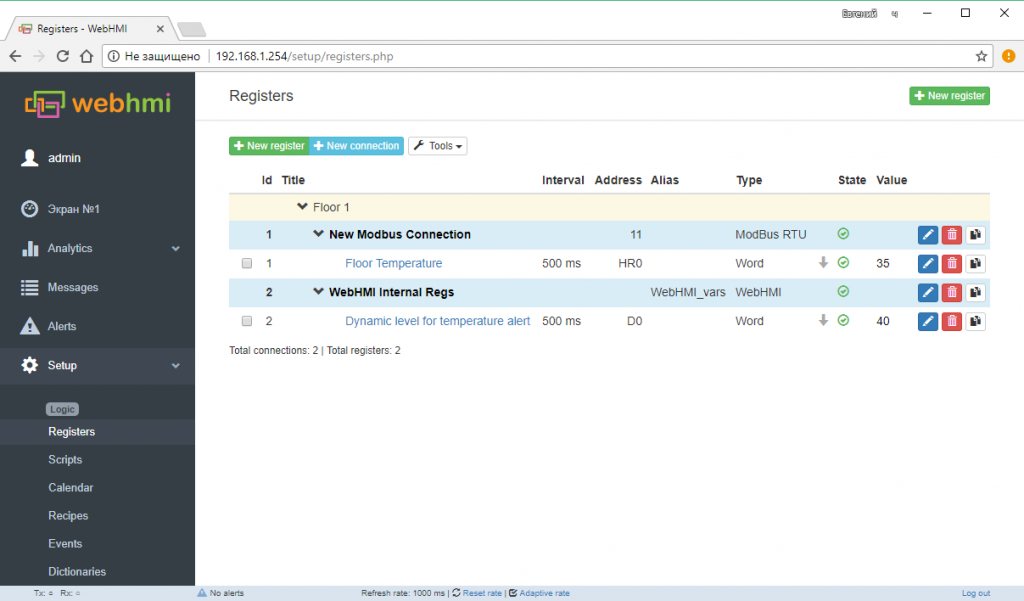
Format of the register list:
- ID - A unique register number in the project.
- Title - Name of the connection / register
- Interval - polling interval for the register
- Address -Address of the register according to the protocol used (for connection - network address)
- Script alias - Variable name for use in lua scripts
- Type - Register data type (for connection - protocol type)
- State - The poll of this register (connection) by the driver is enabled or disabled. By clicking on this icon, you can enable or disable polling for this connection or register. To the left of the status sign is the priority of the poll (dash - normal, up arrow - high, R - read on demand)
- Value - Displaying the current state of the register, a convenient function for debugging - you can immediately see the correctness of the setting and the presence of a connection
- Edit, Delete, Clone buttons - corresponds to editing, deleting or cloning register(connection).
Group Operations
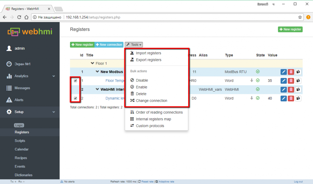
In the list of registers and connections, you can perform group operations - their import, export, enable / disable and reassign the connection for the selected group of registers.
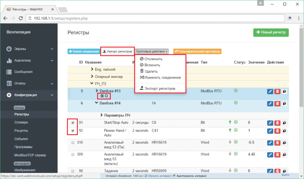
Bulk actions menu for the selected register group allows to:
- Disable or Enable polling
- Delete
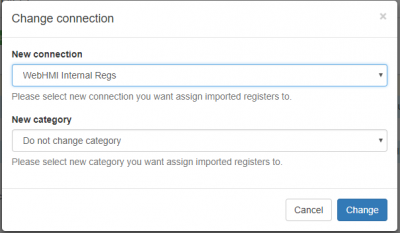
- Move to another connection (Change connection)
- Export registers - This operation exports a list of registers into a csv file, which can later be conveniently edited in a table processor (Open Office, Google sheets, etc.), using the automation capabilities of table processor operations. An example of opening an exported file in the Google sheets application (When opening a file in a table processor of MS or Open Office type, you need to specify the format of the separators - commas, UTF-8 encoding.):
Columns of the table correspond to the properties of registers, which are described in the above sections. Thus, you can:
- a) Override any property for the entire existing list or part of it by highlighting a group of registers by a certain attribute, use the auto-substitution capabilities, formulas, etc., and then use the import function to make the necessary changes to the WebHMI project.
- б) Create your own list (use the existing tag table from the PLC project as a template, etc.) and import it into the project.
- в) Store ready lists for devices and reuse them
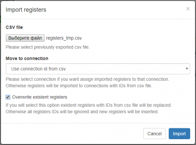
- Move to connection - Allows you to use the connection ID (ID) from the csv file or put registers in an existing connection.
- Overwrite existent registers - If the option is selected, if there are already registers with the given ID when importing the list in the project, they will be overwritten, otherwise registers with matching IDs from the list will receive new IDs.
