External devices connecting
External devices connecting variants
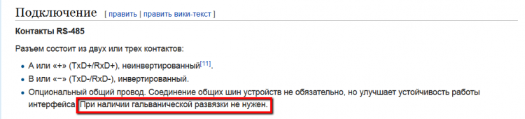
Automation devices and other intelligent devices, which you need to receive the data from, can be connected with the following ways:
- through the built-in RS-485 port, while on the same port you can put devices with different protocols. This is the distinctive advantage of WEBHMI. The port driver can dynamically (on the fly) reconfigure the transceiver.
- Devices with other interfaces, such as RS-232, 422 or additional RS-485 networks, can be connected via USB adapters to the COM port using the built-in USB port.
- Devices with Modbus/TCP protocol can be connected via Ethernet LAN or WAN port.
The configuration of these connections is described here.
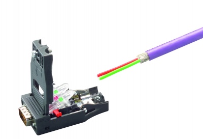
Recommendations for connecting devices with RS-485 interface
Wiring diagram of WEBHMI to devices with RS-485 interface.

Probably (if you already have experience with this interface), after reading the phrase RS-485, you immediately decide to use a 2-wire circuit, connecting to the standard terminals A and B, since only 2 wires are really enough to transmit the signal (a lot of specialists adhere to this opinion). However, this is a generally accepted error. The EIA/RS-485 standard says that 3rd wire is needed:
Sources for the formation this fallacy can be:
- online documentation on the topic:
- some automation devices that have only two terminals for connecting RS-485 on board.


- widely distributed cables for RS-485, having only two wires.
- interfaces microchips manufacturers manuals


- a positive experience of using a 2-wire circuit
- etc.
In fact, it turns out that:
- Informal documentation
- A device with 2 terminals implies the connection of the programmer with a short wire at a low exchange rate
- The cable manufacturer does not remind the buyer that measures to ensure the "equalization" of the common points of the transceivers have not been canceled and they are spelled out in the operating manuals on the devices (using a separate wire or planting "general" on "clean" ground)
- The manufacturer of the microchip combines the principal and functional circuits for simplification of perception
- The 2-wire circuit worked on a table, on a short wire, or on a long wire with a favorable electromagnetic environment
Thus, for a reliable connection it is necessary to use a 3-wire circuit.
The operation of the three-wire circuit is shown in the following figure:

Here Vos is the transmitter bias voltage (measured relative to the common and midpoint of the voltage divider with the same shoulders connected to the A and B outputs), Vgpd is the voltage between the "common points" of the transmitter and receiver, Vnoise is the voltage of the electromagnetic " line, Vcm is the common-mode interference voltage applied to both inputs of the receiver, which adds up as Vgpd + Vos + Vnoise.
The transmitter modulates the differential voltage, forming a signal. The receiver must recognize this signal in the presence of strong interference, and it does this very effectively, but within certain limits. The voltage values for the transmitter and receiver are limited by the standard and range from -7 to + 12V (+/- 7V with respect to the 0..5V signal). In reality, in addition to interference, between the common points of the receiver and transmitter there may be a potential difference of the "ground" Vgpd, which is applied through the outputs of the shaper to the inputs of the receiver. In case of exceeding the Vcm of the above levels, communication becomes unreliable or even disappears.
The induced interference is effectively suppressed by a screen grounded at one point. Interference through difference of potentials "common" points suppresses the third wire, closing the currents generated Vgpd, which otherwise would have been input currents lines A and B the receiver. The
As for the 2-wire circuit of the isolated RS-485, it is also unstable for the following reason. The system can be under parasitic induction in this case, but the current noise "general form" always eager to go back to the source, no matter where and how the chain captures interference, ie, including return through an isolated "general" scheme. This point can in turn become a source of electromagnetic interference for another part of the electronic circuit (for example, through capacitive parasitic links).
A large explanation of the role of one wire is given only to save the user from the loss of valuable time for setting up communications.
In addition, on long lines and at high exchange rates, it is recommended to use a matched cable (twisted pair on the screen, 120 ohm impedance) and termination resistors at the ends of the network segment.
Connection Diagnostics
First of all, after connecting the device and creating a connection, you can create a register in a known state, for example, the bit "always on", etc. After the register is created, its value (Value) will be displayed with the register list:

Перечеркнутое соединение означает, что связи нет. В случае отсутствия связи в первую очередь еще раз стоит проверить кабель и соответствие настроек с обоих сторон.
Помочь разобраться с вопросами связи на встроенном порту RS-485 помогут диагностические светодиоды TX/RX на передней панели - при нормальной работе они должны мигать поочередно. При отсутствии RX - понятно что устройство не отвечает вообще, т.е. возможно неправильно настроен формат или скорость обмена. Если светодиод RX мигает аритмично, как бы "пробиваясь" через равномерное мигание TX скорее всего дело в наличии сильных электромагнитных помех, необходимо выполнить рекомендации под подключению RS-485.