Translations:Подключение внешних устройств/2/en
Материал из WebHMI Wiki
Recommendations for connecting devices with RS-485 interface
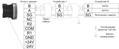
Wiring diagram of WEBHMI to devices with RS-485 interface.

Probably (if you already have experience with this interface), after reading the phrase RS-485, you immediately decide to use a 2-wire circuit, connecting to the standard terminals A and B, since only 2 wires are really enough to transmit the signal (a lot of specialists adhere to this opinion). However, this is a generally accepted error. The EIA/RS-485 standard says that 3rd wire is needed:

Sources for the formation this fallacy can be:
- online documentation on the topic:
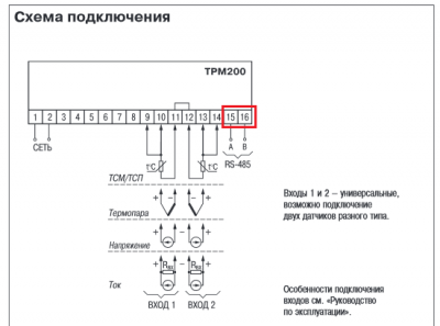
- some automation devices that have only two terminals for connecting RS-485 on board.
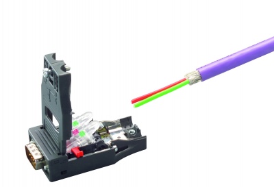
- widely distributed cables for RS-485, having only two wires.
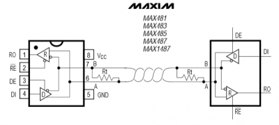
- interfaces microchips manufacturers manuals
- a positive experience of using a 2-wire circuit
- etc.
In fact, it turns out that:
- Informal documentation
- A device with 2 terminals implies the connection of the programmer with a short wire at a low exchange rate
- The cable manufacturer does not remind the buyer that measures to ensure the "equalization" of the common points of the transceivers have not been canceled and they are spelled out in the operating manuals on the devices (using a separate wire or planting "general" on "clean" ground)
- The manufacturer of the microchip combines the principal and functional circuits for simplification of perception
- The 2-wire circuit worked on a table, on a short wire, or on a long wire with a favorable electromagnetic environment
Thus, for a reliable connection it is necessary to use a 3-wire circuit.
The operation of the three-wire circuit is shown in the following figure:


